
I'll wire it up tonight or tommorrow night and test it out.

So one pin both "turns on" the power 115VAC to the Power supply to the Amp/motor boards and "removes" the ground that generates an eStop fault. Well at least a portion of it untill I reached the concusion that if I input 24vdc to the first pin of the "P3" set of pins, that will charge the coils of both "K1" and "K3" relays and that will inturn charge the coil of the "K2" relay. I tracked the wiring of the board last night. You are probably very busy, but if you can spare any more time I’d really appreciate your knowledge or any suggestions that you have. I’m grateful for the help that you already gave me and when I get home and sit down with it and the components it may solve my problem.


The move + direction part I think I got wired up correctly. I’m still trying to get them to power up and thus lock the axis handles from movement. So by ”turn-on” servos I mean …prior to when my mill with Anilam control died when I reset the servos they “locked” the axis’s in their current position, then if they got a move + direction command they moved. Did you reuse the power supply, amps and servos? If you did, how did you wire it to “turn on” the servos? I’m brand new to milling and even more new to CNC if that makes any sense. The board has a 24VDC input as well and therefore might have a 24VDC output via relay. The other one or both relays must also do something as well. I tried wiring it direct with a toggle switch (bypassing the relay board) but it still didn’t charge the servos. I thought one relay would connect the 115VAC power to the bridge rectifier. As near I can tell, the PCB board on the lower left has three relays that “turn on” the power supply (bridge rectifier + big honking capacitor) for the amp boards. The whole bottom part of your picture looks like my past and current set-up as I didn't change any of that stuff.
Anilam series 1100 control manual#
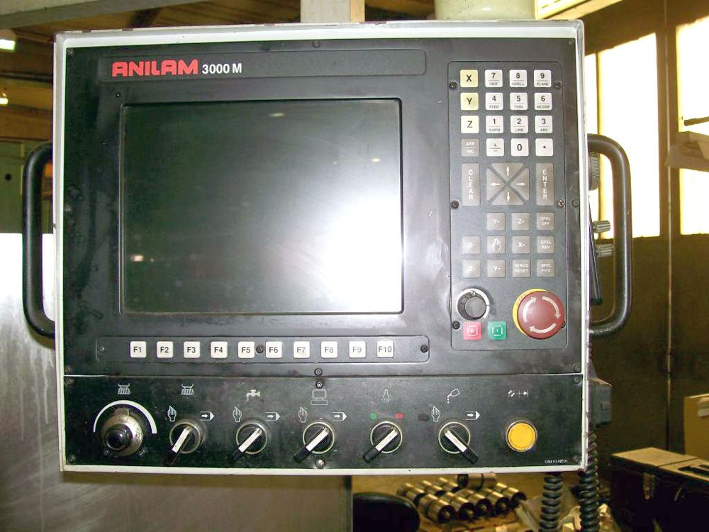
Basically I now have a manual mill with DRO. The computer, the Galil (motion control board), the software, the limit switches, and the encoders all worked on the first try. I used a Galil DMC-4040 motion control board and a new computer but was hoping to reuse everything else (servos, amps, PS, encoders). Its slow going and finally this Thanksgiving 4-day weekend I had some time to try and fire it up. I'm at work now I think it was an Anilam 1100M. I'm retrofitting a Fryer bed-mill which had the identical looking setup. Servo Encoder Feedback DB9 ( From Motor & Encoder Harness )ġ ORANGE ( * +200VDC )Ģ ORANGE ( * +200VDC )Ĥ GRAY ( * GROUND for 200VDC )ĥ GRAY ( * GROUND for 200VDC )ħ BLUE ( ? Servo Motor Drive )Ĩ BLUE ( ? Servo Motor Drive )ġ0 VIOLET ( ? Servo Motor Drive )ġ1 VIOLET ( ? Servo Motor Drive )Ģ RED ( * Axis Signal +/- 10 Volt DC )ģ WHITE ( ? Tach FeedBack )Ĥ GREEN ( ? Tach FeedBack )Ħ BLUE ( * Servo Output Enable )ġ1 BLACK ( * Axis Common, Signal/Analog Ground ) I have attached some PDFs that I found during my investigation and the pinouts list that I was building. We were able to get this functional using pixie 100s (Step Dir to Analog Converters) Pixies are no longer around, but there are other options out there for this.


 0 kommentar(er)
